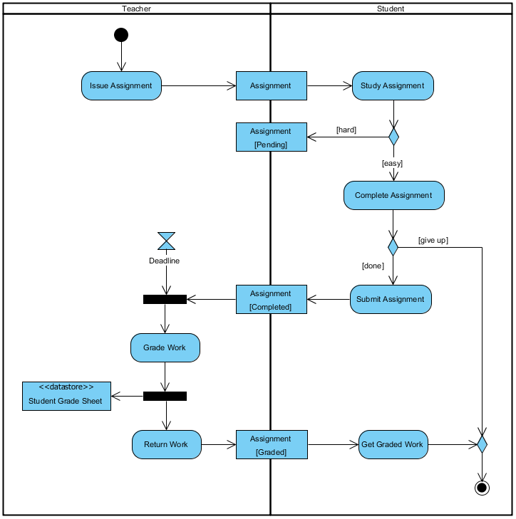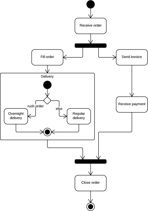

The edges show how the flow of execution occurs. They are a network of nodes connected by edges. The classification of behaviour into actions is called activity. Components in an activity diagram include: i) Activities: Each controls the way in which activities on the road are taking place to ensure smooth flow of traffic. Think of components in the diagram as traffic objects like signals, road markings, zebra crossings and traffic cones. The components of an activity diagram essentially control the workflow of the diagram.

The movement can be sequential, concurrent or branched. Activity Diagram and Its PurposeĪctivity diagrams, simply put, are representations of flow control from one activity to another activity. One of the most important UML diagrams is the activity diagram. Unified Modelling Language (UML) diagram is a pictorial representation of a system, along with its workings, actions, roles and classes, to better visualize and document the system. It also helps in optimization of time and hardware. While there is no wastage of raw materials per-se, it helps in saving thousands of man hours in research and development.
#ACTIVITY DIAGRAM UML SOFTWARE#
This also holds true for software development.

Models are a miniaturized version of the original project based on the blueprint made by the architects. Not only is this a terrible idea based on the amount of raw materials used, it is also an ungodly waste of money.Īnother, more sensible and preferred way to go about things is to plan and make a small model of the hospital, and adjust the various departments accordingly. One way to achieve this is to build a hospital with minimal planning, see if it works, demolish it, re-construct it based on previous operations and repeat till an optimal hospital is built. Furthermore, the hospital needs to be designed such that there is minimal transit time from one room to another so that the patients can have better chances of survival. The hospital needs to have rooms built to handle specialized equipment like MRI machines and CAT scan machines. The focus of this paper is on consistency between the UML diagrams to Z Schema, and then verified by using the Z / EVEs tool.Imagine you are tasked with building a big hospital. This paper proposes an approach involves the combining UML use-case diagram and activity diagrams with Z language for formalization of Library Management System (LMS). Therefore, an integrated between UML specification and formal specification is required to reduce the requirements' ambiguity and error, and to improve the quality and security of software systems. It applied in early stages of Software Development Life Cycle (SDLC). On the other hand, formal methods are techniques and tools use the mathematical notations, and they involve the precise syntax and semantics of the unambiguous software requirements specification. However, the ambiguity of semantics and the absence of consistency among UML diagrams lead to lack of precisely defining the requirements of a system. Unified Modeling Language (UML) is the effective standard for modeling object-oriented software systems.


 0 kommentar(er)
